Pet Auto Feeder With Fusion 360 4 Steps Instructables
Introduction Fusion 360: Threads with Joints and Motion Links thehardwareguy 56.2K subscribers Subscribe Subscribed 617 Share 23K views 4 years ago #CAD #fusion360 #autodesk
Half thread screw Fusion 360 YouTube
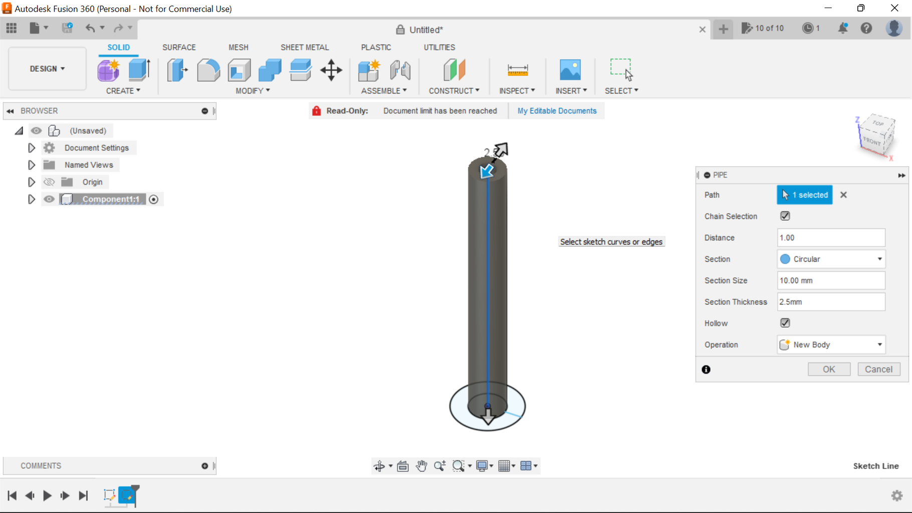
For bolt connections, use the Cylindric type of constraint (joint, coupling) in combination with the linked Rotation joint in Fusion 360 to constrain the nut movement along the length of the bolt thread. Set the desired joint limits and angular speed of the nut rotation. The detailed workflow and parameters of the ribbon Assemble are.

Nuts And Bolts Software WERSHOFT
Intro Fusion 360 Tutorials Threads & Joints Short to Ground 1.96K subscribers Subscribe 557 42K views 6 years ago Fusion 360 Tutorials This tutorial shows how to design threads and make a.
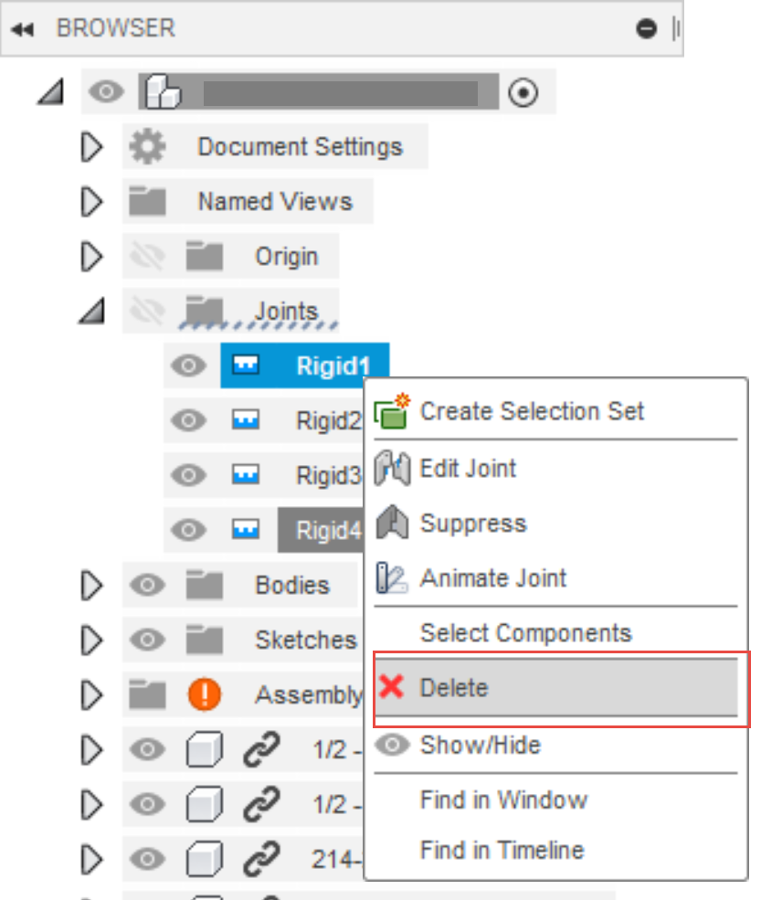
How to delete a joint in Fusion 360
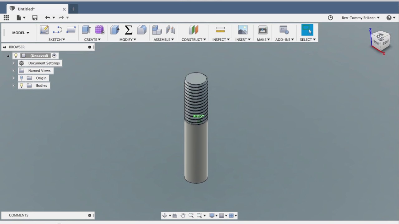
When you model the part that it screws into do not create the threads, just create the hole for the threads. Then position the threaded part in the hole and use Modify-> Combine-> Cut to cut the threads perfectly into the lower part. Make sure to check "Keep Tools". This will give you perfect alignment, but probably too perfect a fit to print.

Fusion 360 Tutorial Screw Threaded Parts YouTube
3. Precise Control Over Motion. Motion Study grants you precise control over the motion of components, allowing you to showcase intricate movements effortlessly. 4. Showcasing the Animation Through Rendering. Take your animation a step further by rendering the motion study. Fusion's rendering capabilities let you create stunning visuals to.

fusion 360 screw hole Ericvisser
Solution: To Animate a joint in Fusion 360: Solution 1 Navigate to Assemble > Motion Study. Select the Joint. Add Distance and step. Play the component with the different mode. Solution 2 Navigate to Animation. Navigate to Transform tab and select Transform Component. Select the component to move. Add distance to Slide.
DiscoverThat Journal Fusion 360 nuts and bolts
You can use both the Joint and As-Built Joint tools to create 7 joint types in Fusion 360. Each joint type uses different degrees of freedom to define motion. You can also add Motion Limits, use Contact Sets, Rigid Groups, and other component relationships in combination with joints to create more realistic movement in your design. Rigid

Fusion 360 UJoint Tutorial YouTube
Dec 18, 2023 Products and versions covered Issue: Need to find information and how to use the joints commands in Fusion. Solution: For adding Joints to component assemblies in Fusion use the following Instructional information and tutorials - Fusion Product Documentation: Joints Was this information helpful? Need help? Ask the Autodesk Assistant!

Revolving the set screw Assemble Parts and Components in Fusion 360 YouTube
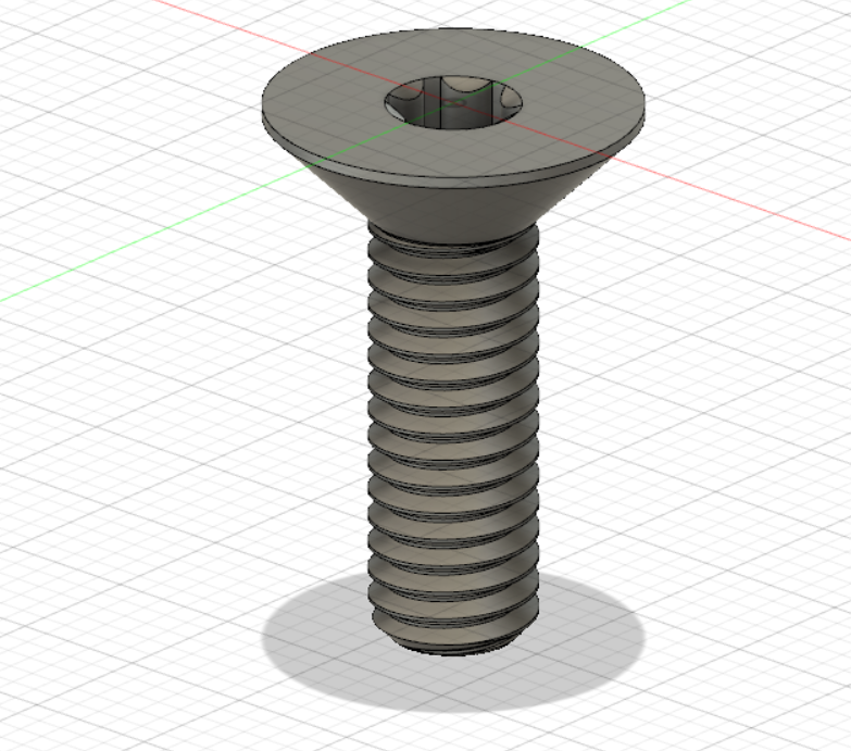
In the Modify section, select the Offset Face command. Turn off the nut and select the 4 faces of the screw thread (be careful to select all 4 faces) and assign an offset of -0.1 mm (you can adjust this for your printer tolerance, but 0.1mm usually works very well). Then press OK. Repeat the procedure for the nut.
Design of Screw Feeder in Fusion 360. YouTube
We're back with another CAD tutorial! Today we are going in depth to learn the basics of using Joints in Fusion 360 to create assemblies. Joints are one of m.

How to Create Threads Fusion 360 Tutorial 14 YouTube
22 Share Save 1.3K views 2 years ago Fusion 360 for FTC This is the eighteenth video in the Fusion 360 for FTC. In this video we use the skills learned in the previous two days to.
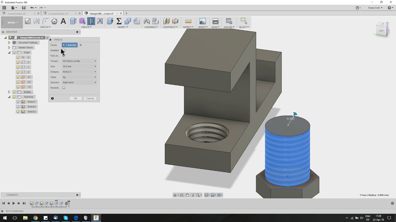
3D Printable Hanger with Screw Fusion 360 Tutorial YouTube
Using the McMaster-Carr feature within Fusion 360, you can insert all sorts of little models like screws, nuts, bolts, and whatever else you may need.If you.
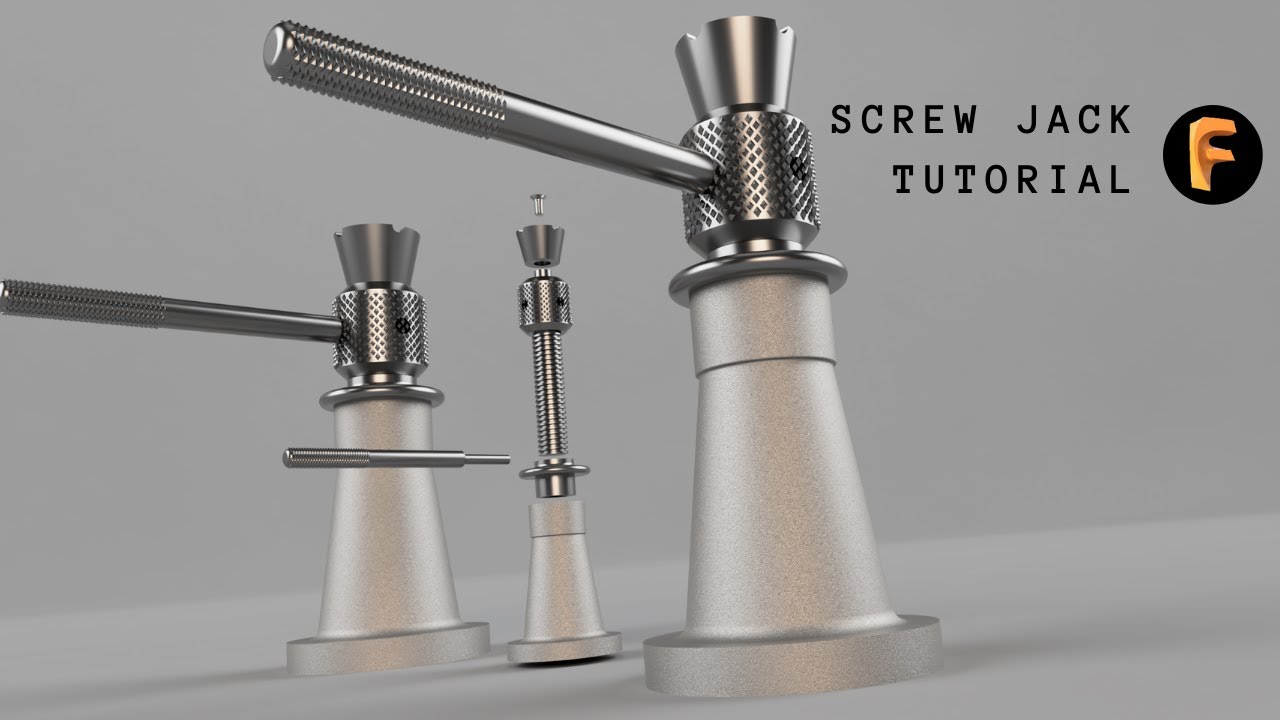
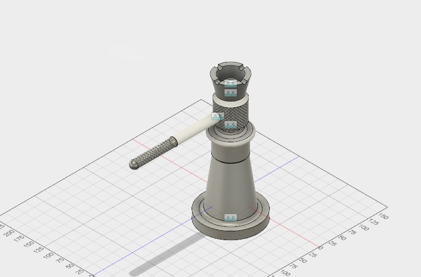
FUSION 360 SCREW JACK DESIGN ASSEMBLY TUTORIAL YouTube
About joints in Fusion 360 Fusion 360 defines relationships between components by using joints and as-built joints, and joint movement provides degrees of freedom. With other CAD tools, you use a constraint or mate to limit one or two degrees of freedom at a time, then add constraints or mates until you have enough degrees of freedom.
Screw JackAutodesk Online Gallery
Description. You can define your customized screw with the following Parameters: Screw Name: Name of the Body. Head Diameter : Diameter of the cylinder head. Body Diameter: Diameter of the body shaft. Head Height: Height of the cylinder head. Body Length: length of the body shaft. Hexagon Diameter: Diameter of the inner Circle of the hexagonal.

Universal Joints in Fusion 360 tutorial YouTube
joints available in Fusion 360 assemblies. In subsequent lessons, you apply many of these joint types to models. Learning Objectives • Recognize the degrees of freedom available in different joint types. • Use options within joints to refine their behavior. The completed exercise. 1. Use New Design from File tool to open the Vise.f3d file. 2.

Screw Organizer (Fusion 360 Tutorial) Organization, Fusion, Tutorial
Fusion 360 will find a midplane between the two angled faces to create a joint origin. TRY AUTODESK FUSION FOR FREE Tags and Categories Uncategorized When assembling components, some designs require components to be centered between two faces. There are many different approaches to this depending on your CAD background.
